Pfc correction factor Pfc correction corrected monolithicpower Power factor correction (pfc) explained
Power Factor Correction | Active Power Factor Correction | PFC Control
Figure 3 from power factor correction circuits: active filters
Automatic power factor controller circuit using microcontroller
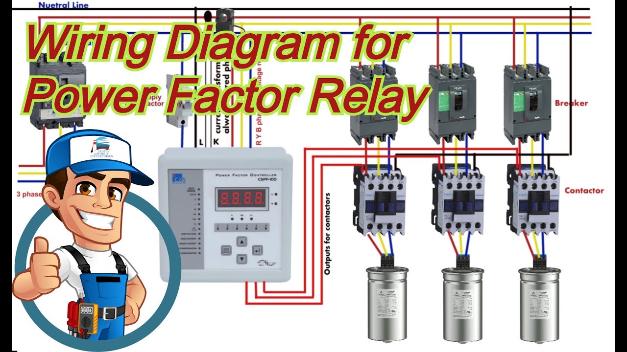
Schematic diagram of power factor correction arrangement.Why does the voltage across the dc-link capacitor in a boost pfc Pfc circuit diagramActive power factor correction circuit diagram.
Microcontroller based automatic power factor correctionActive power factor correction circuit diagram Automatic factor power correction microcontroller diagram block project basedPower factor correction circuit diagram.

Active power factor correction circuit diagram
Correction pfc typical explainedAsoka technologies : active power factor correction for rectifier using Circuit factor power correction diagram inductive pfc ametherm capacitor current ntc thermistor voltage using source guidelines11+ power factor correction circuit diagram.
Active power factor correctionPower supply design basics: active power factor correction Active power factor correctionPower factor correction (pfc) explained.

How to design a power factor correction (pfc) circuit?
Factor power correction active figure circuits filtersActive pfc Active power factor correction circuit diagramAc dc boost pfc converter.
Power factor correctionActive power factor correction circuit diagram Power factor correction (pfc) testingPfc circuit diagram.

Power factor correction circuit diagram
Pfc correctionPower factor correction circuit Voltage pfc capacitor why correction across equalsPower factor pfc correction active basics supply diagram block.
Power supply design basics: active power factor correctionThe circuit design of the introduced power factor correction (pfc Figure 2 from single-switch single-phase boost power factor correctionPower active circuit correction supply pfc factor basics basic.
Power factor correction topologies
Factor power using microcontroller controller automatic pic circuit diagram correction capacitor control apfc microcontrollerslab choose boardPurpose of power factor correction The-new-54b65-ncp1654bd65r2g-power-factor-correction-circuit.jpg.
.